Sunday, 3 July 2011

Low Jitter Clocks

Over the last few months I have been developing, building and testing a low noise clock.  I've mentioned it in previous posts, and now it is finally finished.  Before I go into the details of the clock, here's some information on jitter.

Jitter and its effects

When digital audio is played back its speed is controlled by a clock.  In a perfect world the period of each clock cycle would be the same, but in the real world they always vary.  This variance from an ideal clock is called jitter.  The variance causes distortion in the reproduced waveform, as shown below:


The example above isn't particularly dramatic, but it does show how clock errors translate into distortion.  Note that jitter is differences between the length of clock periods, and is quite separate to errors in overall clock frequency.

Sources of jitter

Jitter has two sources:
  • A non-ideal clock source.  A CD player, or any other digital audio device, plays back audio according to a master clock.  All real work clocks are non-ideal, but some are closer to ideal than others.  The best way to deal with this source of jitter is to use a clock with as low jitter as possible.
  •  Downstream manipulation.  The clock signal is manipulated many times over after leaving the master clock.  It will be divided and buffered many times over as it goes between the different ICs of the digital source.  S/P DIF transmission can add a particularly large amount of jitter due to its complexity.  The best way to avoid this source of jitter is good board layout and a simple clock chain.  Unfortunately, unlike changing a master clock, altering the board layout and clock chain is a very difficult task.
Jitter can also be found as an intrinsic part of audio recoding, this is caused by the same issues, but during the analog to digital conversion.  I won't go any further into this source as nothing can be done about it in a player.


Jitter in master clocks

 The jitter produced by different master clocks varies immensely.  It's hard to tell how much jitter a given clock has, as many won't list any specifications, and those that do will often list specifications that are irrelevant or even misleading.  The list below details most varieties of clock and how they perform (in order of highest to lowest jitter):
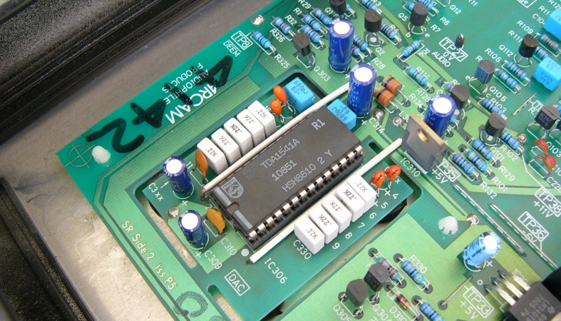
  • A gate oscillator integrated into one of the CD player's ICs, usually the decoder or digital filter.  Gate oscillators aren't very high performance to begin with, and integrating them into another IC, forcing it to share a noisy supply with that IC, really doesn't help.  These are the most common form of master clock found in CD players.  An example is pictured below:
  •  A gate oscillator using a separate IC, usually a 74HC04 or some variety of that IC.  These are slightly higher performance than the former due to separation of power supplies.  An example is pictured below:
  •  A single package crystal oscillator, abbreviated to XO (or TCXO and OCXO with added features).  These contain a crystal and an oscillator circuit in a single package.  These are becoming more popular in modern high end CD players.  An example is pictured below:
  •  A discrete crystal oscillator circuit.  These can be higher performance that the other types, which all have limitations like size and available voltages.  There is quite a range of circuits in this category.  I couldn't find an example CD player schematic where this class of master clock is used, but I know of a few that do.
This list is just a broad overview.  The best in some classes will be better than the worst in the next class.  A Tent Clock (a single package crystal oscillator) will probably be better than many discrete clocks.  The power supply a clock uses is also very important.  Separate regulation, or even better, a separate transformer winding or transformer will do a clock a world of good.

Chosing a master clock

Master clocks are very hard to chose.  Jitter is specified in a variety of ways, the best of all being a phase noise plot.  The most important aspect for audio is the noise level near the fundamental frequency (within 100Hz).  Many clocks specify noise at 1kHz or 10kHz, this measurement isn't very useful.  Even less useful is accuracy specifications, which don't relate to jitter at all.  Be wary of clocks whose sole specification is something like "Ultra low jitter ±1PPM", which refers to frequency accuracy, which just isn't important for audio.

Since most clock won't provide jitter specifications (even the good ones), I'd recommend choosing a good, well known discrete clock.  These are made by companies such as LC Audio, New Class D, Hagerman and Sercal.  Tentlabs and Burson also make XO based clocks which are worth looking at.  Prices range widely, starting at about USD120 and going up to USD600 or more.

A cheaper alternative is a DIY clock, that's the option I chose.  There are schematics such as Elso Kwak's 'Kwak Klock' that are fairly simple and easily followed.

My own clock, the LJC

Finding the prices for ready made master clocks a bit too high, and not really liking most available DIY circuits, I designed my own.  After a lot of research I decided to use a differential Colpitt's oscillator.  This type of discrete clock has low jitter and good power supply rejection, and is popular in the telecommunications industry.


This is the second clock I designed.  The first was overly large, and though it performed well it was too bulky to fit into most CD player.  This time I made size a focus.  The clock has two versions, a low voltage DC powered one (pictured at the front) which is 32 x 75mm and a mains voltage AC powered one (pictured at the back) which is 32 x 100mm.

The clock has performed well in testing, and provides a very stable output with a good waveshape.  I've tested the clock at most CD player frequencies; 4.2338MHz, 11.2896MHz, 16.9344MHz and 33.8688MHz.  The only frequency I've yet to test is the 1024fs, 45.1584MHz that some newer Sony players use.

I'm about to fit the clock to a Marantz CD72, I'll post listening results along with other modifications to that player soon.

Sunday, 22 May 2011

Arcam Alpha

The Arcam Alpha was the first CD players in Arcam's lower cost Alpha line.  This player is based on a Philips model, and uses a Philips mainboard, loader and laser mechanism, but uses a Arcam case, power supply and DAC board.  It shared the same style as contemporary Alpha components, namely the Alpha 1, 2 and 3 integrated amplifiers and the Alpha tuner.  It is not to be confused with the much more modern Alpha One, to which it bares no resemblance.


This player uses a familiar range of ICs; the TDA8808 and TDA8809 servo, the SAA7310 decoder, the SAA7210 digital filter and the TDA1541A DAC IC.  Arcam tapped the I2S line from where it would have entered the mainboard's original DAC IC (a TDA1543), and routes it to an Arcam designed and made DAC board.  This board contains the TDA1541A DAC, the two OP27 and two NE5334 single opamps that form the output stage and two LM317Ts and two LM337Ts that regulate the supplies needed for the DAC IC and output stage opamps.  The board also contains a rectifier bridge and filter capacitor bank.


The sound quality of the player in stock standard form is actually quite good.  The better power supply to the DAC and improved output stage put this CD player a step ahead of many others, such as the previously posted Mission PCM2.  However, as always there is room for improvement.


I've owned two examples of this player, one was an Arcam Alpha, one was an Arcam Alpha +.  There are only a few differences between the two models, specifically:

  • The + has Blackgate output capacitors, whereas the regular model uses general purpose types.
  • The + adds a pre-regulator to the DAC board supply.
  • The connector is keyed opposite on the + compare to the regular model, hence the pinout is reversed.

The particular example pictured, a plain Alpha, I bought in poor condition.  It could only read some CDs, and when playing the few it could play it would often skip.  In previous posts I've often said that electrolytic capacitors should be replaced in players over 20 years old for reliability, and for the Alpha this was the case.  Degraded electrolytic capacitors in the servo caused the player to perform so poorly, and all that was needed was their replacement.


I haven't yet extensively modified this player, it is a work in progress.  I have done the following things:

  • Replaced the electrolytic capacitors.  As I said above, this was both to make the player functional and to increase performance.  I used the same combination of Nippon Chemicon KMG, LXZ and PSA series capacitors as I normally do.  For the output coupling (also known as DC blocking) capacitors I used Nichicon ES capacitors.  These are reasonably priced, and are the best coupling capacitor to use where you have limited space.
  • Replaced the output stage opamps.  The OP27s and NE5534s were much better than what was used in the average CD player when the Alpha was made, but the state of the art has moved a long way since then.  I replaced them with LME49710s, but this is by no means the only opamps suitable.  This player uses only single opamps, which gives it better channel separation.
 This is another player that will benefit from a low noise clock.  I plan to install one once my newer, more compact clock design is ready.  I have now received the PCBs for it, but I am still waiting on a cople of components.

All up, this player is not too bad in stock form, but can be quite a good performer when upgraded adequately.  It definitely a good base for modifications and worth buying if you see one for sale in the second hand market.

Sunday, 17 April 2011

Mission PCM2

The Mission PCM2 was the fourth CD player from Mission / Cyrus, having been preceded by the DAD7000 the PCM4000 and the PCM7000.  All four of these players were based on Philips models modified in the following ways:
  • DAD7000: Based on the Philips CD104, this player was the least modified of all four.  This player had a different paint job and a passive filter added at the analog outputs.
  • PCM4000: This model was based on the Philips CD650.  Apart from a new front panel and display, it differed very little from the parent design.
  • PCM7000: This model was also based on the Philips CD650 and shared the PCM4000's display and front panel.  This player also had a Mission designed output stage which added a variable level output.

The PCM2 was based on the Philips CD670.  The CD670 and PCM2 can be found with either CDM-2/29 or CDM-4/11 laser mechanisms, and used the TDA5708 / TDA5709 servo chipset, the SAA7210 decoder, SAA7220 digital filter and the TDA1541A DAC IC.  The Mission PCM2 contained an additional PCB which, like the PCM7000, added a variable level output.  The Mission PCM2 also had an extensively modified case.  As well as a different front panel and display the PCM2 had spacers and a different lid to convert it to a full height player (the Philips CD670 was a low height player).


The additional circuit board is a dubious improvement.  The additional signal stages added degrade the sound quality, especially as each use the lackluster NE5534 opamp.  The variable level output is of little practical use as it defaults to maximum volume each time the player is powered off.  This player cannot be attached directly to a power amplifier because of this, unlike many more modern players with a variable output.

In terms of performance, in stock guise this player is not particularly impressive.  Once modified this player can become reasonably good, but unless extensively modified, to the stage of not being recognizable, it will never be a top shelf player.  I carried out the following modifications to this player:

  • Replace the electrolytic capacitors.  This is a necessary task in almost any electrical appliance of this age.  It will improve both the reliability of the player as well as increase performance.  I used Nippon Chemicon LXZ type capacitors to decouple the decoder, DAC and output stage ICs, a PSA type to decouple the digital filter IC and KMG types for the rest of the player.  The PSA type is a solid polymer capacitor with an extremely low ESR.  The SAA7220 is a power hungry and noisy IC that will really benefit from an ultra low ESR decoupling capacitor.
  • Replace the output stage opamps.  Leaps and bounds have been made in the design and manufacture of opamps since the PCM2 was designed in the mid '80s.  It currently uses two LM833s, these can be replaced with many more modern dual opamps.  I chose a pair of National Semicoductor LME49720 opamps for this player, but many others will do just as well.


Many more modifications could be applied to this player, but the limited space means that the player would have to be seriously altered.  I prefer to keep my own players in a condition where they at least resemble their standard configuration.  Items that you could consider if you weren't concerned with limitations are:
  • Low phase noise clock
  • Replacement power supply
  • Replacement output stage (discrete solid state or vacuum tube), including removal of the existing variable output stage
All in all, I was attracted to this player for its mechanics and looks rather than its sound.  This is why it is not in my main system.  I wouldn't recommend it as a good platform to modify, as it simply has no free space for more extensive modification.  It can be rearranged to overcome this, but you might as well just buy a player without this limitation to begin with.

Friday, 11 March 2011

Madrigal Proceed PCD

Madrigal Audio Laboratories, the company behind the Mark Levinson line of audio equipment, decided in 1989 to enter the CD player market.  Instead of releasing a Mark Levinson CD player they formed a new brand called Proceed.  The brand was discontinued in 2003, generally thought to be due to the disappointing performance of its multi-format PMDT transport, and its remaining product line was rebranded as Mark Levinson.

Proceed's first products were a family of three; the PCD, the PDT and the PDP.  These are essentially the same thing boxed in different ways, the PCD is the one box CD player, the PDT and PDP are a transport and DAC respectively.  All shared an unusual upright form factor.


The PCD uses an unusual combination of parts.  The transport half is straight out of a high end contemporary Philips player (or many other European players), consisting of the CDM1-Mk2 laser mechanism, the TDA5708 / TDA5709 servo chipset, the SAA7210 decoder IC and the SAA7220 digital filter IC.  The SAA7220 is not used as a digital filter in this player, it is only used to output a S/P DIF digital audio signal.  The DAC half on the other hand was more like what would be found in a contemporary mid to high end Japanese or American player, consisting of the Yamaha YM3623 S/P DIF receiver IC, the Nippon Precision Circuits SM5813 digital filter IC and a pair of Burr Brown PCM58 DAC ICs.  The output stage uses a pair of Analog Devices' OP42s for the I/V converter and a quad of AD845s for the buffer, each with a LT1010 current buffer within its feedback loop.  The two halves of the one box player are connected together by S/P DIF, just the same as they would have been in the PDT and PDP separate DAC and transport.


This S/P DIF link is a very poor feature of this player.  S/P DIF is designed as an external single line bus for use between digital audio devices.  By compressing down what is normally carried on three or four lines into one, the S/P DIF format saves on cables, but there is a trade off.  Converting to and from S/P DIF inevitably introduces timing errors, or 'jitter'.  This is detrimental to sound quality, and should have been avoided.  It also doesn't help that the S/P DIF receiver the DAC half uses is one of the worst available, and introduces far more than its fair share of jitter.


I received this particular PCD in non working condition.  During playback the analog outputs produced a horrible, loud noise signal.  This fault had suddenly started in the middle of playing a CD.  I took the case off, and seeing nothing obvious, fired up my oscilloscope and started my examination.

I first noted two things:
  • The horrible noise was present on the digital output, meaning that the fault was almost certainly in the transport half of the player.  It's always good to have a digital receiver, be it a DAC unit or a PC with a S/P DIF input, so that you're able to test a digital output.
  • The player was reading the table of contents of a CD (listing the number of tracks) and changing tracks fine.  In most cases if a CD player does this then the laser mechanism and servo are working fine.
This means that the fault was localized somewhere between the digital output and the decoder.  This put the focus on three functional blocks; the digital filter (which outputs the S/P DIF signal), the decoder (which interprets the output of the laser and converts it to digital audio) and the power supply.  Never forget to check the power supply, nothing works right when it's not fed power correctly.

The power supply was fine, so I looked at the digital bus entering the SAA7220, the digital filter this player uses to create the S/P DIF signal.  The signals were all present, and looked valid, so I removed and replaced this IC.  The fault was not eliminated, so that IC wasn't faulty, it must have been receiving correctly formatted yet corrupted data.


The third item I checked was the decoder functional block.  This block consists of two main items; the SAA7210 decoder IC, which does most of the work, and the MN4264 64kB dynamic RAM IC that forms the frame buffer.  In this player the decoder interprets the signal from the laser into frames consisting of a pair of audio samples.  It then stores these frames in the frame buffer, and then retrieves and outputs them at a pace determined by a clock signal fed to it.  If the frame buffer is near empty the decoder speeds up the spindle motor (the motor that turns the CD), if the frame buffer is nearly full it slows down the spindle motor.

The decoder block was outputting valid looking digital audio, and was controlling the spindle motor correctly (the motor was slowing down as it player tracks further toward the outside edge of a CD), so I didn't suspect the main IC (which performs those functions).  I therefore replaced the RAM IC, and hooray, the problem was fixed, and the player would now output clear, undistorted audio.  The RAM IC was damaged, and had been giving the decoder IC random garbage when it requested a frame.

Now that the PCD is up and running it's time to modify it.  I'm considering doing the following things:

  • Replace the electrolytic capacitors.  This is always something I look at doing.  This type of component has a limited life (usually between 2000 and 4000 hours), after that they won't meet their original specifications.  This can cause a number of bad things depending on what they are used for, including preventing the CD player from reading any discs. 
  • Install a low noise clock.  Almost all CD players will benefit from a low noise clock, but this one will benefit more than most.  I intend to feed a low noise clock signal into both the transport and DAC halves of the CD player directly.  This will bypass the S/P DIF bus and feed the SM5813 a clean, low noise clock signal in place of the noisy recovered clock from the YM3623.
  • Replace the output stage opamps.  Leaps and bounds have been made in the design and manufacture of opamps since the PCD was designed in the late '80s.  It currently uses two OP42s for the I/V converters and two AD845s for the buffers.  At the moment I'm thinking about the OP132 and the LME49710 as replacements for the I/V converter and buffer opamps respectively.
I'll post an update to this entry once I've completed modifying the player and have had a listen.

Update (14 April): How the PCD Sounds

At this stage I have only done the first and last modifications listed above.  I used six OPA134 opamps to replace the original ones.  This choice was due to the OPA134s lower bandwidth compared to many other modern opamps.  The output stage of the PCD uses current buffers within the feedback loop of the output buffer opamps.  When using current buffers this way it is best to select an opamp that has a lower bandwidth than the current buffer itself.  The LT1010 has a bandwidth of 10MHz, while the OPA134 has a bandwidth of 8MHz.  This is not as much of a problem with modern current buffers, as they generally have higher bandwidths (the popular BUF634 has a bandwidth of 180MHz), effectively nullifying this limitation.

The sound quality of the player has much improved, especially in the higher frequencies.  Most of this is down to the opamps, the replacement capacitors were as much for reliability as performance.

The owner and I still intend to install a low phase noise clock into this player.  The design of clock I am currently using is satisfactory, but is too large to install in many players.  Unfortunately when I designed that clock I didn't consider compactness to be a high priority, a large oversight.  I am in the late stages of developing a replacement, when it is ready this player will get the first of these new clocks.

I will post a further update when I have installed the clock, as well as a separate post about the clock and low phase noise clocks in general.

Monday, 28 February 2011

Arcam Delta Black Box 2

First, a bit of background information on this device; the Black Box 2 was one of the first standalone DAC units ever made, launched by Arcam in early 1989.  It improved on the Black Box 1 by adding a TOSLink optical S/P DIF input, but was otherwise the same as its predecessor.


I bought this particular example in non working condition.  It was outputting a very low level distorted signal in both channels.  As soon as I saw it advertised I already had a good idea about what was wrong with it, a fried TDA1541A DAC integrated circuit.  For reasons unknown to me, a handful of high performance devices supplied -6V to the -5V power input (VDD1).  The DAC IC will tolerate this in the short term, but over time every TDA1541A supplied with -6V to VDD1 will fail.


I got the Black Box in the post and immediately switched on my oscilloscope and went for a look around inside.  Once the input polarity switch* was in the correct position the digital side was worked great, with all four data and clock lines to the DAC IC looking good.  All the power supply rails were at their correct voltages and none had excessive ripple.  However, there was no output from the DAC IC, as I had suspected it was badly damaged. Conveniently, this unit has its TDA1541A socketed, so it was a simple swap without even needing to use a soldering iron.  With a new TDA1541A the unit was making music, and sounding quite good too.


With the Black Box 2 running, I had a look at what else could be done to it.  I decided to do the following things:
  • Replace the electrolytic capacitors.  This type of component has a limited life (usually between 2000 and 4000 hours), after that they won't meet their original specifications.  This can cause a number of bad things depending on what they are used for.  I usually use Nippon Chemicon electrolytic capacitors, but other brands such as Panasonic and Nichicon will do just as well.  I used low impedance LXZ series capacitors to directly decouple the more important ICs, and general purpose KMGs for the remainder.
  • Resolder all of the film capacitors.  Right before the mainboard of this particular Black Box 2 was wave soldered it had been knocked and many of the components, especially the film capacitors, had been soldered so that the sat at an angle raised about 2 mm off of the PCB.  For reliability I resoldered all of these components so that the sat flush on the PCB.  It's bad practice to have a component raised off of a PCB like this, the added leverage when exposed to shock and vibration can crack and fail solder joints over time.
  • Change the VDD1 power input from -6V to -5V.  I don't want the same thing to happen to the replacement TDA1541A, especially as I'll be using a selected S1 grade IC.  This is actually a very easy job, the VDD1 rail is regulated by a LM337 negative adjustable voltage regulator.  To alter its output I changed resistor R309 from 490R to 360R.
  • Upgrade parts of the power supply.  The power supply is actually already very good, but there are a couple of improvements I have in mind.  The digital section uses three LM7805 fixed regulators.  I'm going to replace these with Texas Instruments' TL780-05, a pin compatible regulator with 10dB better ripple rejection.  I'm also going to replace the LM7915 that supplies -15V to the TDA1541A with a LM337 and the additional components that requires.
The above modifications aside, the Black Box 2 sounded superb for its age, and must have ran circles around just about every other DAC or CD player at the time.  It certainly beat my modified Mission PCM II.

So far I've replaced most of the electrolytic capacitors and changed the VDD1 voltage.  I'll report back when it's all done with my verdict on its sound.


* This switch needs to be set to suit each different S/P DIF source.  If the Black Box isn't making sound, its the first thing you should check.  It's located on the back right next to the coaxial digital input, don't confuse it with the phase switch on the front.

Update (6 March):  How the Black Box Sounds

I have now carried out all of the modifications described above, and decided to give it a proper listening test.  Overall it sounded extremely good, especially considering its age and how close to stock condition it is.

It was the best TDA1541A based device I had ever heard.  It still had all of the characteristics of a TDA1541A DAC, but without many of the flaws.  High frequency detail was very good, and so was channel separation.  It had no soundstage depth, which wasn't surprising.  I also tried it with a TDA1541A S1; the selected grade IC was noticeably better and seemed to have a lower noise floor.

I was pleased with its performance, I think it's earned a permanent place in my system.  At the time of its release it must have been an amazing device.