Saturday 16 August 2014

Marantz CD84

Philips acquired Marantz in 1980 to try to broaden their appeal to the high end audio market.  This opened an interesting period that covered most of the CD player era, where both Marantz and Philips were designing separate but similar lines of players and releasing them under their own or the others name.  This led to pairs like the Philips CD473 and Marantz CD65DX, externally very different, but internally the same (and both made by Philips) and the Marantz CD72 and Marantz CD60, externally almost identical, but internally completely different (the CD72 being a Marantz, and the CD60 actually a Philips).

Aside from this, there were a few models that were fairly unique to their own brand, and the Marantz CD84 (and the similar CD74) was one of these.  It doesn't have a close Philips equivalent, and apart from the core chipset, it's almost entirely Japanese.


Externally, it has a number of unusual features; on the back, above the analog outputs, there are a pair of potentiometers that allow you to set the level of each channel separately, as well as an 'easy bus' connector (no, I don't know what it does either, probably something to do with recording CDs).


Inside, the player is laid out with the main transformer and loader on the left, and most of the electronics on the right.  The decoder and servo boards sit in a metal frame with the component side facing each other.  The loader is a standard Philips type that can be found in the CD104 and other players.


The servo is fairly similar to that found in other players using the CDM1, but uses a mix of Hitachi, Sharp and JRC parts.


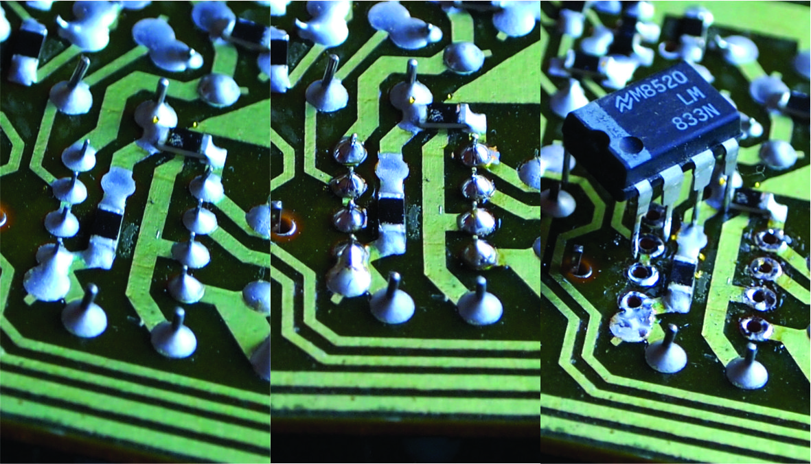
The decoder board is again fairly similar to other players using the fist generation Philips chipset, but executed with Japanese, rather than European, parts.  In particular, note the epoxy dipped reed relays, film and copper foil capacitors, Anritsu relay and JRC opamps.  Being a very early player, the TDA1540s are a ceramic DIP package type.


Behind this frame is the player's power supply.  The huge heatsink is a reminder of how inefficient the first generation chipset in the player was.  These ICs consumed 500 to 1000mW each, and there's a few of them.


That lump on the back of the player isn't a transformer, it's a mains filter.


Here's the most interesting thing about this player though; a completely separate Japanese version of the CDM1.  In the CD84's service manual it's referred to as a CDP-3.


The most striking feature from the top is the turned brass spindle.  This version also has a cast aluminium alloy chassis, but there isn't the webs like the Philips made one.


On the bottom side there's a different preamplifier and motor driver board and a different spindle motor.  This CDM1 uses a brushed motor, but it's Japanese made, and different from brushed motor used in the CDM0.  The actual swingarm seems to be the same, apart from the oversized brass nut, I'm not sure what the purpose of that embellishment is.

Apart from the CD74 and CD84, I'm not sure where else these were used.  The Marantz CD94 seems like it would, but as far as I'm aware it doesn't, it just uses a regular Philips CDM-1.  If anyone knows of others, please let me know.

I'm not intending on modifying this player at all, as there are other much more suitable players for that.  The last notable thing about this player is that unlike most other players this old, it actually works.  No modifications, no replacement parts.  Very impressive.

Sunday 26 May 2013

Philips CD150

The Philips CD150 was one of the first cheaper CD players that Philips made.  This player was released in 1985; CD players were no longer new and the technology was starting to mature.  Quite a few steps had been taken to lower the production costs of this player and players like it, including:

  • A new laser mechanism.  The CDM0 and CDM1 have a prototype feel to them, they're large, they have many parts and are made of expensive materials.  The CD150 uses the CDM2.  For the CDM2 both the chassis and laser swingarm arm made of plastic and the spindle motor is a much more compact PCB based brushless design.
  • An IC based servo.  Earlier CD players had complex servos based on discrete semiconductors and low level integration (such as opamps and logic ICs).  The CD150 uses the new TDA5708 photodiode signal processor and TDA5809 radial error signal processor ICs.  This cut down both the component count and the PCB area the servo occupies.
  • A standard PCB layout.  This player has three significant PCBs; the servo board (underneath the laser mechanism), the mainboard (on the right side of the player) and the front panel board.  Philips made a fair few players during this era with the same layout.  Compared to earlier CD players with multiple stacked PCBs these were easier to construct and service.
  • A cheaper case.   Most of the other changes were positive, this one isn't.  The CD150's case is fairly well designed, but it lacks rigidity.  When the lid is removed it's laughably flexible, and the larger full width players, like the CD350, are even worse.

As you might notice this image is a bit different to what I normally upload.  It's on my workbench, this post will be about how to do a capacitor replacement as well as some basic upgrades.  This player is a good candidate, it's stock standard and still working, but it's starting to struggle to read a CD.

Tools

This job requires tools that are specific to electronics.  Some are essential, some are optional.  We'll start with the essentials:
  • A soldering iron.  You'll need an iron suited to electronics with a reasonably fine tip with a power of 15 to 30W and a ceramic element.  Don't use a large high powered one with a nichrome element, they're best used for burning marks into wood.  I used to use an Antex XS25, it was okay.  You'll also need a stand and a wet sponge to clean the tip.
  • Solder.  Leaded solder is easier to work with and more forgiving of poor technique, so I'd recommend that, though I realise it's hard to get anything other than lead free in some places.  Whichever you get, make sure it's a good brand solder with multiple flux cores.  I use Henkel Multicore 362, 60/40 leaded solder with a rosin flux.  The solder diameter should be 0.75mm (22SWG) or less.
  • Desoldering tools.  There are a couple of options here.  You can use either desoldering wick (sometimes called desoldering braid) or a desoldering pump (sometimes called a solder sucker).  I mostly use a desoldering pump, maybe take a look at how they're used later in this post to decide which you prefer.  For the wick, only buy a name brand, cheap brands don't work.  Don't buy brand name wick from China on eBay, it's often counterfeit and again won't work.  I use Edsyn Soldasip SW091.  Generic solder pumps will work okay, but name brand ones work better.  I use an Edsyn Soldapullt SS750LS.
  • Cutters.  Try to get a pair or proper electronics cutters, rather than diagonal pliers.  I use Hakko CHP-170 cutters, they're cheap and they work very well.
  • ESD protection.  This is an item many overlook, but it's essential, at least if you want the CD player to work after you've finished with it.  You're going to need a mat and a wrist strap with a cord.
  • Screwdrivers.  Most of you will already have a general purpose screwdriver set, but for older Philips players you'll need a Torx T10 driver as well.

Additionally there are a few optional ones:
  • A soldering station.  An ordinary soldering iron doesn't work very well.  If the power is low it will be too cold to solder larger components properly.  If the power is to high it'll overheat smaller components and burn of the flux.  A soldering station is temperature controller, and varies the power to its soldering iron so that you can solder both larger and small components well.  I use a classic Hakko 936, which is a good soldering station.  You can pick up one of the second hand market or buy its replacement new, the Hakko FX888.  Goot also make nice soldering stations, as do Pace and Metcal, though I only have personal experience with Hakko and Goot.
  • Test equipment.  In an ideal world you wouldn't need it, but if your repair is unsuccessful, you're blind without it (literally, electrons are very hard to see).  The main instruments I'd use when troubleshooting a CD player are a multimeter and an oscilloscope.
Materials

Okay, you've got the tools, now you need the materials.  The first step is forming a bill of materials, or BoM (a list of what electronic components you need).


There are a few was to make a BoM.  The service manual is available for free online for most of these older Philips players, including the CD150.  Nostatech is a great resource for Philips service manuals.  You can make the BoM simply by reading the manual, which will list all of the components.  However, my prefered method is to remove the PCBs and read the values directly off the capacitors.  Often the service manuals won't list the voltage rating (which you need to know), and sometimes aren't consistent with the actual device.  When making a BoM for a capacitor replacement you need to note the capacitance and voltage rating of each component.  You may also want to note the diameter if the capacitor is in a tightly packed area (so that you don't get a replacement that is to large to fit) and its function.  Here is an example, the BoM I wrote for the CD150:

Mainboard:
6800u/16 1 2416
1000u/16 1 2417
330u/25 2 2402, 2418
100u/25 1 2419
47u/10 7 2320 (DAC dec.), 2321 (DAC dec.)2388, 2396 (digital filter dec.), 2397, 2410, 2411
47u/25 10 2309,  2362, 2365, 2380 to 2383 (opamp dec.), 2412, 2413, 2414
100u/10 2 2384, 2385 (both output coupling)
10u/63 2 2330, 2331 (both DAC bias filtering)
220u/63 1 2420
1u/63 1 2313
Front:
47u/25 3 2052, 2056, 2058 (all axial)
1u/63 1 2053 (axial)
Servo:
47u/10 2 2104, 2107
33u/16 1 2103
47u/25 1 2173
1u/63 1 2174
1.5u/50 1 2159 (bipolar)
220u/10 3 2127, 2138, 2140


As you can see above, I've identified a few capacitors that I'll give special treatment.  These are:

  • DAC, digital filter and output stage opamp decoupling capacitors (2320, 2321, 2393, 2380 to 2383).  These capacitors are located close to their respective components and have a large impact on the quality of power supply that each component sees.
  • Coupling capacitors (2384, 2385).  These are used to block any DC at the players output, so that the player only outputs AC.  These are critical to sound quality.  They can be replaced with film capacitors, but their size adds another set of issues, so I'll stick with compact electrolytic capacitors.  
  • DAC biasing capacitors (2330, 2331).  These are part of the circuit that nulls the offset of the DAC ICs current output.  A low impedance type will help here.
  • Axial capacitors (2052, 2053, 2056, 2058).  This form factor, where the leads are attached to both ends of the body, has gone out of common use in favour of radial packages, where both leads are attached to one end of the body.  Axial capacitors are used in all three boards in this player, but in most cases a radial capacitor will fit okay.  On the front panel board there isn't room to stand a radial capacitor upright, so I'll use axial replacements.  You could use radial capacitors, but it will look untidy and possibly be less mechanically reliable.
  • Bipolar capacitor (2159).  This capacitor filters the output of the radial motor driver, and can cause problems in some cases.  I prefer to replace it with a film capacitor, but a replacement bipolar electrolytic will also work.
So that covers the type of capacitors needed, now I need to determine the capacitance and voltage ratings.  I won't get replacements that exactly match the originals, it just isn't necessary.  When choosing a replacement's capacitance, you should stick to the same value as the original unless you understand what its function is, and the implications of making a change.  For example, increasing the value of the four 100uF opamp decoupling capacitors isn't a bad idea, but increasing the value of the 1uF capacitors (part of the microcontroller reset circuit) could disable the player.

When choosing a replacement's voltage rating, in general sticking to a rating the same or higher is fine.  However, there are a couple of exceptions:
  • Don't increase the voltage rating excessively.  If you try to replace a 220uF/10V capacitor with a 220uF/200V one you may find it simply won't fit, as size increases with voltage rating.  Electrolytic capacitors also diminish in performance in some respects with voltage rating, the sweet spot is 35V.
  • Some capacitors have a voltage rating far higher than necessary.  Often these are low capacitance, and are only available in high voltage ratings.  An example in the CD150 is the two 1uF/63V capacitors.  They only have 5V across them, so it would absolutely fine to replace them with 1uF/50V or 1uF/35V rated capacitors.  To consider reducing a voltage rating, you must know exactly what the capacitor will be exposed to.
Now that we've established what capacitances and voltage ratings we need and what special requirements some particular capacitors have we can actually make a final BoM to order.  Here's what I came up with for this player:

1u/63 2 EKMG500ELL1R0ME11D Nippon Chemicon
1u/63 1 MAL203038108E3 Vishay BC
1.5u/50 1 BSME500ELL2R2ME11D Nippon Chemicon
10u/50 2 ELXY630ELL100MEB5D Nippon Chemicon
33u/35 1 EKMG350ELL330ME11D Nippon Chemicon
47u/25 3 MAL203036479E3 Vishay BC
47u/35 13 EKMG350ELL470ME11D Nippon Chemicon
56u/35 7 ELXY350ELL560MFB5D Nippon Chemicon
100u/10 2 UES1E101MPM Nichicon
100u/35 1 EKMG350ELL101MF11D Nippon Chemicon
220u/25 3 EKMG350ELL221MHB5D Nippon Chemicon
220u/50 1 EKMG500ELL221MJC5S Nippon Chemicon
330u/25 2 EKMG250ELL331MHB5D Nippon Chemicon
1000u/16 1 EKMG160ELL102MJ16S Nippon Chemicon
6800u/16 1 EKMG160ELL682MLN3S Nippon Chemicon

This list was not only based on what I prefer, but what was available to me at a good price.  By default I chose Nippon Chemicon KMG series.  These are a general purpose 105°C capacitor from a brand I trust.  I normally use 105°C rated capacitors, they're only slightly more expensive than 85°C rated ones, but will last much longer.  For the critical decoupling capacitors I chose Nippon Chemicon LXY series, a long life low impedance type.  For the DC blocking capacitor I chose Nichicon ES series, a good quality bipolar electrolytic that sounds better than most.  For the bipolar capacitor in the servo I chose Nippon Chemicon SME-BP series, a general purpose bipolar type.

You've got to make decisions about what you buy based on what's available to you.  It's no use making a list like this without knowing that they'll be in stock at a reasonable price.  Which electronics seller will be best for you depends on your location, the following are worth considering; Farnell / element14 / Newark, Digikey, Mouser and RS.  These serve the Asia Pacific region, there are more that serve other parts of the world.  I also use PartsConnexion for audio-specific components.  I don't recommend eBay, it looks good on the surface, but the value coverage and quality is quite patchy.

As part of this I'll also replace the output stage opamps.  This player originally used LM833s, one per channel.  One half is the I/V converter, the other half is a buffer.  Though most modern dual opamps in an 8DIP package share the same pinout, they're not universally interchangable.  I decided on an OPA2134 as a replacement, it has good performance, it is not too fast, it is unity gain stable (the buffer has unity gain) and it is widely available.  There are many good opamps, but unless you understand what to look for in a replacement and have an oscilloscope to check for stability, I'd stick to the OPA2134.

Desoldering

Now that you've got a pile of fresh capacitors, it's time to remove the old ones.  The boards in this player are actually double sided, but they're not through hole plated, so the techniques are the same as what you'd use on a single sided board.  At the same time you're desoldering the components you'll need to think about how you'll know what values go where and their polarity when you come to soldering in the new capacitors.  The easiest way is to only desolder and replace one value at a time.

To note polarity you can mark the board (I put a dot next to the negative lead, the one marked by a stripe or ring on the capacitor).  I also like to take a photo before the replacement that I can compare with the end result.  It's best to rely on these method rather than to use the diagram in the service manual or the board's silkscreen (on more modern PCBs than this example), as both of these are often wrong.  The service manual digram for the CD150 shows the wrong polarity for both 2380 and 2309.

On these types of boards I'll use two different techniques, depending on how the components were mounted.  For smaller components, like resistors, diodes, TO-92 transistors and electrolytic capacitor less than 8mm, the legs of the components were bent over to hold them to the board during wave soldering.  Larger, heavier components were simply placed, their own weight would be adequate to keep them in place.


On the smaller components, the leads are usually accessible from the top side.  I cut the leads as close to the board from the top side.  I then add fresh solder to the joints from the bottom side then remove both the solder and lead remained using the desoldering pump.


On the larger components, where the leads aren't bent, I'll add solder to the joints from the topside, then use a desoldering pump to remove the solder.  If this is done cleanly, the component should pull out easily from the top, or even drop out.  If the component isn't free, check that each lead is loose when pressed with, say, a fine screwdriver.  Add fresh solder and reapply the desoldering pump as necessary to free each lead.

Soldering

Like I mentioned above, you'll probably want to install the new components as you remove the old ones.  How to solder is something that has been done many times, this video here is quite good, if you're unfamiliar with soldering I suggest you watch it.  The main thing is to check that the component you're installing is the right value and the polarity is correct.

Unfortunately these older PCBs are quite fragile.  When you're desoldering components it's easy to damage the tracks or pads on the board.  If you do this, don't ignore it.  the best way to fix the problem is to bend the lead through the damaged pad and solder it to another pad that it would normally be soldered to.  Even though I was very careful with the CD150's board, half of a pad on one of the capacitors lifted.  Here is a photo of how I repaired that:


Here are the boards after the replacement:


Powering Up

Now the the repair is complete it needs to be tested.  I recommend that you once again check that all the components are installed with the correct polarity.  If the polarity is wrong the electrolytic capacitors may explode, and the opamps would be destroyed.

Reassemble the boards into the player and reconnect the cables.  If you're unsure about the cabling, check the wiring diagram in the manual.  You should also check the motion of the laser mechanism's swingarm when you have screwed the servo board to it.  It should swing freely throughout its arc, if it doesn't you may have installed a capacitor that is too tall.  If that is the case, remount the capacitor on its side or use an axial leaded capacitor.


When testing a new repair, it is good practice to slowly power it up using a variac while monitoring its current consumption.  However, a CD player is a low power appliance, so that's not strictly necessary.  If you don't have a variac, power the player up while wearing safety glasses and prepare to turn it back off if anything sounds, smells or looks wrong.  Don't connect the outputs to anything during this first power up.

If all goes well, connect the player to the rest of your sound system, put a disc in and try it out.  Check it plays both pressed CDs and burned CD-Rs and check it plays well without skipping from the first to the last tracks.  Hopefully it all works fine.  If it doesn't, it's troubleshooting time.  A CD player is a fairly complex piece of electronics, so troubleshooting a bad repair is going to be a hard ask for a beginner.  It's best to start out with a cheaper player like a CD150, wrecking one of these is no great loss.  Wrecking something like a Marantz CD16 on the other hand... (I've had to recover one of these from a upgrade gone wrong before).

Friday 11 January 2013

Marantz CD17

The CD17 is a mid to high end CD player that Marantz released at the end of the 90's.  It marked a downward change in the quality of Marantz's top line players, which had previously featured swingarm laser mechanisms, diecast chassis bases, metal loaders and other esoteric features.  The CD17 still looks good from the outside and performs well, but is obviously much more driven by build cost.


The CD17 was available for a number of years in a few variations, as detailed below:

  • CD17.  The base model, it uses a CDM12.1 laser mecanism, a SAA7372 servo and decoder, a SM5841 digital filter, a SAA7350 noise shaper, a TDA1547 DAC and an output stage based on NJM2114s and HDAM modules.
  • CD17D.  This player uses the same PCB as the CD17 but adds a digital input using a TDA1315 S/P DIF receiver, allowing use of the player as a DAC.  The TDA1315 and its associated parts are not fitted on the regular CD17.
  • CD17a / CD17 Mk2.  An updated version of the CD17, it uses a VAM1201 laser mechanism and TDA1307 digital filter (in place of both the SM5841 and SAA7350).  The TDA1307 was designed specifically for the TDA1547, but wasn't found in many players, most used an NPC digital filter and the SAA7350 as a noise shaper and upsampler.  The VAM1201 also allows this player to player CD-RWs.
  • CD17Da.  Similar to the CD17D, this player shares the CD17a's PCB but adds a digital input using a TDA1315 S/P DIF receiver.
  • CD17 Mk3.  This player is significantly different to the others, using a different digital filter, DAC and output stage.
I've wanted a player using the TDA1547 for some time, but they're not particularly common and are usually fairly expensive.  There are a huge variety of opinions on the sound of this DAC, the last DAC IC that Philips made for the high end market, but in my experience it is very competent.


This particular CD17 was inexpensive as it wasn't working properly, so I bought it to fix.  It was in good physical condition, and in included the original packaging, manual and remote, but would not read a CD.

Unfortunately, unlike its predecessors, which all used swingarm laser mechanisms, the CD17 uses a cheaper CD12.1.  These mechanisms have an inferior lifespan compared to the ones they replaced, so I suspected the laser had failed.  The upside is that replacements for the CDM12.1 are easily available at low cost.  I used a VAM1202, these are a suitable replacement for a CDM12.1.


At this point I removed the existing laser mechanism.  The CD17 is very serviceable, only three screws and two connectors need to be removed to take out the loader, and you don't need to remove the drawer faceplate.  Removing the laser mechanism from the loader is somewhat annoying, it is attached by four rubber grommets which need to be removed with care, as they are easily torn.

On examining the old mechanism I made a foolish decision.  Time and time I have told people to change the whole laser mechanism and not to replace only the laser head.  However, I looked at the old one, and the traverse seemed to be in reasonable condition, with no gear discolouration or apparent wear, so I ignored my own advice and bought a VAM1202 laser head.

On receiving the laser head I fitted it to the old traverse and fitted the mechanism back into the player.  It powered up the player and it immediately read the disc (there is no setup when changing a laser with the SAA7372 based servo, the laser power is factory set on the laser head and the other adjustments are done automatically, a great feature).  All seemed well, but shortly into a listening session it skipped slightly, and continued to do so occasionally throughout the disc, at an average interval of about 5 minutes.  I removed the loader and carefully lubricated the transport again, but that didn't help.

I went back on eBay an purchased another VAM1202, complete with a traverse this time.  I fitted the new complete laser mechanism, the skipping disappeared are the player now works well.  The first laser head isn't a complete waste, as the laser head will serve as a useful spare in case the other fails prematurely, as they sometimes do.

At this point I gave the player a good listening test.  I compared it directly against a Marantz CD16, the CD17's direct predecessor.  The CD16 features a similar chipset, an SAA7310 decoder, SM5803 digital filter, SAA7350 noise shaper and two TDA1547 DACs (one per channel, differential output).  Both CD players sound quite good, but the high frequency output of the CD17 was notably rougher and more metallic than the CD16.

After listening to it I had a think about what I wanted to change on the CD17.  Though this player was built to a budget, it's still higher end than most of the players modified so far in this blog, and many items that I'd normally address just aren't as critical here.  The passives are of generally high quality, and the player isn't as old as many I service, so there isn't the need to replace components due to age.  Here are main things I think could be improved:

  • Output stage: As standard, the CD17's output stage is actually quite good.  The passives are of a very high standard, including mica capacitors and what appear to be thin metal film resistors.  The opamps used, one NJM2114 per channel, aren't bad, but they could be improved with more modern types.  I'm not going to change them right now, but it's something I may do at a later time.
  • Final output: While the main part of the output stage is good, I'm not so enthusiastic about the final output.  At the output of the 'HDAM' discrete buffer the signal passes through a bipolar electrolytic capacitor, followed by two transistor shunts to ground for muting, a ceramic capacitor to ground and then the outputs.  None of this is ideal, and my plan is to replace this entire section with an auxiliary PCB.  This PCB will include film coupling capacitors, muting relays (a reed relay per channel to shunt the signal to ground) and 100pF polypropylene film capacitors to ground.  All in all the same  functionality, but with less compromise.
  • Low jitter clock:  The clock system in this player is far below optimal.  Initially I intend to replace the original clock source, but I also plan to change the clock distribution entirely at some point in the future.

Installing the Clock

At this stage the only thing I've done is install the clock.  I do plan on doing the two other things mentioned above, but at a later date.  I also intend on this section being a loose guide for those who are installing the clocks they bought in the groupbuy.

This first thing I did when installing the clock is familiarise myself with how the clock is generated and distributed in the player.  This was complicated by the fact that this player's service manual is not available.  The manual for the CD17 Mk2 can be downloaded, but it's quite different in some areas.  I've drawn a diagram showing the clock scheme of the CD17 below (items in grey not fitted):


The SAA7372 decoder generates the clock, then buffers it to a 74HC257 multiplexer.  This IC is redundant in models without a S/P DIF input, and is always set to the CD input.  The output of this multiplexer is then fed to both the SM5841 and the SAA7350.  The SAA7350 then divides the clock in two and feeds it to the TDA1547's two clock inputs.  Most players aren't this complex.

Once I had determined where the player's original clock was located on the PCB I decided where to mount the clock PCB.  I picked a place that was clear and as close to the clock as possible.  It's important that the signal cable between the clock and the receiving IC is as short as possible.  This cable shouldn't be more than 150mm.  I drilled holes through the player's chassis and mounted the clock with two M3x6 machine screws and an M3x10 threaded hex spacer at each corner.


To connect the clock into the player I removed C111, C112, R108, R109 and X101, and fed signal to pin 21 of the SAA7372 (XIN).  To do this I prepared a coaxial cable with an SMB connector at one end and separated and tinned ends at the other.  I soldered the centre conductor to the now free crystal pad that connects to pin 21 of the SAA7372.  I scraped the soldermask off a groundplane area next to that pad and soldered the shield to it.  I then secured the joint between the cable and the PCB with glue.


I connected the DC supply to both sides of capacitor C854 (minding polarity).  I installed a snap on ferrite on this cable.  I then rechecked my wiring, powered up the player and ran through a function check.  Job done.


A few things to watch when installing a clock:

  • Identify the master clock.  A CD player will often have more than one crystal, but in most cases only one has an impact on the sound quality.  Make sure you're replacing the correct one.
  • Check IC voltage tolerance.  Many modern players use ICs that operate from 3.3V power supply rails.  These ICs may not tolerate a 5V level signal, and you may need to build / buy a clock with a 3.3V level output.

Monday 23 January 2012

Mission PCM7000

The Mission PCM7000 is a player I've already mentioned in this blog; it's the direct predecessor to the Mission PCM2.  The main difference between the two is the player that they are based upon, for the Mission PCM2 it is the Philips CD670, while for the Mission PCM7000 it is the Philips CD650.  Electrically the two players are almost identical, but physically they don't share a chassis, loader or laser mechanism.


The PCM7000 uses the same rather unhelpful variable volume output stage.  It's a resistor attenuator using CMOS switches, which isn't too bad, but it has no non-volatile memory and resets to maximum volume each time the player is power cycled.


As it stands this player is rather lacklustre, similar to the PCM2.  However, it doesn't have the same drawback the PCM2 does; there is actually space for extensive modifications inside the PCM7000.


I intended to remove the variable volume output stage and replace it with a new PCB.  At this stage it'll incorporate the following:
  • A digital filter, probably a SAA7220, there aren't many alternatives.
  • A DAC, probably still the TDA1541A, as I want to maintain some of the original flavour of the player, but I'm also thinking about using a SM5803 / PCM1701 combination.
  • A discrete output, based on either the Pass D1 or EVUL's CEN / SEN.
  • Power supplies for all of the above.
I'll write more on this post as I make progress, but it's still in the early stages right now.

Sunday 13 November 2011

Philips CD101

I was quite excited when one of these came up for auction, they're not a particularly common player here in New Zealand.  The Philips CD101 isn't quite the very first Philips player, but it's very similar to the CD100 which was number one.  The two players share the same PCBs and the same frame, but the CD100 uses a CDM-0 laser mechanism and the CD101 uses a CDM-1.  The graphics and lid design also differ slightly, but overall they're very similar.


The particular example I bought was ideal; it was being sold by the original owner, was in perfect visual condition and included the owner's manual and box, yet wasn't working so was still inexpensive.  When it arrived I plugged it in and found it had the exact symptoms I expected.  It would power on successfully, spin a CD when one was loaded and the play button pressed, but it wouldn't read the CD.  These players, like most (but not all) radial armed players, will only spin a CD once the laser has successfully focused on a disc.  If a player will spin a disc, the laser and focus servo are probably okay.  However, when it tried to read the table of contents of the disc the player would track and the radial arm would run out of control, often hitting the end stop quite hard (rather funny to watch).  This meant that the radial servo wasn't running properly.  The likely cause is the recurring defect with these players; expired electrolytic capacitors.

The particular capacitors that cause the failures in these players is the five on the PCB directly mounted to the laser mechanism.  Two of these are decoupling for the ICs, the remaining three are part of the laser supply.  Most of these aren't paralleled with any other capacitor and really need to perform well for the player to work.


I replaced all five, and unsurprisingly the player worked perfectly.  I went on and replaced every electrolytic in the rest of the player, but only the five needed to replaced for it to work.  In terms of sound quality, this player isn't too bad, but it's certainly not high end.  This player was undoubtedly the best in its day, far better than Sony's efforts, but CD players have come a long way since.  Please don't buy into the hype, these players are good considering their age, but will be beaten by any half decent modern player.

The big surprise about this player was how easy to service it was.  Everything in the player screws into a large aluminium casting.  The outer casing is secured by five screws, once it's removed most of the player is accessible.  I've worked on other Philips players of the period and they were much more awkward.


I didn't modify this CD player as I want to keep it as original as possible.  All of the above photos show the player after I serviced it, with the new capacitors in place.

Below is the player's original box, as per request.


Sunday 30 October 2011

Low Jitter Clock Build Guide

Sorry about the lack of posts recently, I've been occupied with setting up a group buy for my low jitter clock, as well as working on some newer designs.  This post is the build guide for that clock.

To build the clock you're going to need the same tools as any other PCB based electronics project.  It's all through hole, but it's at the finer scale end of through hole, so you are going to need a decent soldering setup and good technique.  If you're using leaded solder, a decent electronic specific plug in iron will do, but if you're using lead free solder a soldering station is recommended.  The clock uses JFETs and other static sensitive devices so you'll need a static safe workstation.  A multimeter and oscilloscope are also useful for checking that the clock is working properly, and are very useful if it isn't.  Of course you'll also need the schematic and bill of materials.

There are two versions of this clock, both sharing the same PCB.  They differ on how they are powered, one has a transformer and is powered directly from 220 to 240VAC mains electricity (called the AC powered version).  The other is smaller, having no transformer, and is powered from a 7 to 20VDC supply, usually an existing supply within a CD player.  The DC version draws about 40mA, most CD players will have a supply that can provide that without issue.  When building the AC powered version components D205 and J202 are not populated, when building the DC powered version components D201 to D204, J201, TX201 and VR201 are not populated.

The bill of materials lists a very specific set of parts.  The column labelled 'Order No.' shows the element 14 (formerly known as Farnell) part number, their site will give the details and data sheet on each part.  Here are some comments on parts:

  • Film capacitors: Parts C101 to  C105 are all Wima FKP2, a stacked polypropylene film and foil type.  These are a very high performance capacitor that still have a small footprint.  I'd stick to these, other film types may be too large, ceramic types will fit but won't perform as well.  C202, C203 C205, C208 and C211 are decoupling capacitors, any 5mm pitch film capacitor with a thickness of 2.5mm or less will do here.  I used Wima MKS2 stacked metalised polyester  types.
  • Electrolytic capacitors: I used Nippon Chemicon KZE low impedance high temperature types, except for C209 which is a KMG general purpose high temperature type.   There are plenty of other good options here, such as the DIY favourite Panasonic FMs and FCs or any equivalents from Nichicon, Elna, Rubycon etc.  Stick to capacitors from a reputable brand and don't use extremely low impedance types (such as OS-CONs or solid polymer types) for C210.  High temperature types are worthwhile, they only cost slightly more and will give better reliability, especially in older power hungry CD players which can run quite warm.
  • Diodes: I used MBR1100s for the rectifier (D201 to D204, only used on the AC powered version), similar schottky or soft recovery types will work just as well.  D205 (only used on the DC powered version) is a reverse polarity protection diode, use any 1N400x series diode or leave it out if you like to live dangerously.
  • Connectors: J101 and J102 are the output connectors.  The PCB pattern is a standard RF type and will accommodate SMA, SMB, SMC and other RF connectors.  SMB seems to be the defacto standard for clock in audio, so that's what I used, but feel free to use something different.  It's best to use factory made cable with these connector, there's a whole load available cheaply on eBay.  J201 or J202 is the power input connector (which one you use depends on whether you're building an AC or DC powered version).  It's a standard 5mm pitch terminal block pattern, but will fit 5.08mm (0.2") items without any trouble.  I'd recommend the screw cage types over the screw and protector types, they just work better.
  • Semiconductors: J309s (Q101 and Q102) and TL431s (U201 and U202) are pretty generic easily available semiconductors, my only advice is to stick to good brands (Fairchild, ST Micro, ON Semi, National etc).  The AD8561 comparator (U101) is proprietary to Analog devices, and is not pin compatible with any other suitable candidates, so there's no choice to make here.  The series regulator (U203) can be any of the xx108x low dropout regulator series (such as LD1085, LM1086 etc).  Make sure you buy an adjustable output voltage version, these come in fixed voltage versions as well.  I chose these not because they are low dropout, but because they have integrated protection diodes.  You can use an LM317, which is pin compatible, but you'll have to tack the protection diodes to the underside of the PCB.
  •  Resistors:  I used Welwyn MFR3 0.125W metal film types.  These have body dimensions of 3.5mm long by 2mm diameter, it is essential that this small size is used, the far more common 0.25W types will not fit.  The exception is R101 and R102 which are 10MR.  Generally 0.125W resistors are not available in resistances this high, so 0.25W Welwyn MH25 types are used here.
  • Transformer:  The transformer I used is a Myrra 44091.  Its form factor is industry standard, and is compatible with the Block VB1.5/2/6 among others.
  • Varistor: VR101 is a varistor (used in the AC power version only) that gives the clock some protection from mains voltage spikes, it is optional.
  • Crystal: Obviously a critical component in a crystal oscillator.  Stick to good brands (I use Citizen) and make sure you get the correct frequency for your application.
Apart from being slightly more difficult to solder than other through hole PCBs due to the small size components, construction is fairly straightforward.  I assembled it in the following order:
  • First chose the version you are making.  The PCB has a silkscreened line where the PCB can be cut if you are going to build the DC version.  The photos will show an AC version being built.

  • Solder in the axial components (resistors and diodes), paying attention to the polarity of the diodes.

  • Solder in the film capacitors.

  • Solder in the semiconductors except for U203.

  • Solder in the electrolytic capacitors.

  • Solder in the transformer, U203 and J201 or J202.

  • This point is a good place to pause and test a few things.  The two remaining components, U101 and J101 and / or J102 are expensive and cannot be removed once soldered.  You can power the clock up and test the rest of it here.  First you should double check the polarity of the components shown below:

  • After checking the polarities power up the clock in a safe manner.  I will not give specific electrical safety advice.  If you are not confident in your ability to work safely with mains electricity do not attempt to assemble the AC powered version of this kit.  Use an oscilloscope to check the points shown below.  A sine wave of the same frequency as the crystal should be visible on the two marked points.  The waveforms at the two points will be of opposite phase.  Check the voltage of the other point with a multimeter, it should be 5V.

  • All going well above, solder in U101 and J101 and / or J102.

Hopefully you now have a working low jitter clock.  Thanks to those who participated in the group buy, enjoy your clocks!

Update (06/05/2014):

This design has been around for over three years now, and it was time for the first major redesign.  The main thing I did to improve on the original was to separate the AC power supply from the clock.  I found I barely ever built the AC powered version of this clock because it meant having a mains voltage AC cable running through the middle of the player or a long clock output cable, neither work well.

In this version the clock PCB can sit where it's needed, the AC to DC power supply board can sit with the player's original PSU, and an innocuous DC power cable can cross the player.  Overall the size has increased a little, but the clock on it's own is smaller, and I think overall it's easier to fit into a player.

As for building it, the new version is essentially the same to build; the main exception is the regulator.  In the newer version I've mounted it to the PCB with a machine screw.  It's more robust and lower profile.  It's easy to assemble, just follow these steps:

  • Take the regulator and bend the leads 90° right after the step where the leads become narrower (ignore that the pictures show a LM337, it's just the TO-220 device I had to demonstrate with).  Take the supplied M3x10 machine screw and place it through the PCB from below and thread one of the M3 nuts onto it and tighten. 
  • Place the LM1085 over the machine screw with its legs inside the pads.  Place the M3 lock washer over the LM1085 onto the machine screw, then thread the second nut onto the top and tighten.  The stack should be: head of M3x10 machine screw, PCB, M3 nut, LM1085 tab, M3 lock washer, M3 nut.
 
  • Flip the board over and solder the three pins.

Enjoy this new version of the clock!

Sunday 28 August 2011

Marantz CD72

The Marantz CD72 is the top model in the CDx2 line.  This product is from the era where Marantz was owned by Philips, and hence it uses many Philips made components.  All of the players in this line were of the same configuration; they used a CDM-4/19 laser mechanism, the TDA8808 / TDA8809 servo chipset, the SAA7310 decoder IC, the SM5840 digital filter IC and the SAA7350 noise shaper and DAC IC.  Unlike previous digital filter ICs used by Marantz, the SM5840 does not output a S/P DIF signal.  A separate IC, the PCF3523, is used to format the digital output in this player.


I've never been a huge fan of the early DACs using the 'bitstream' concept.  The SAA7350 used in the CD72 was Philips' second try at making a bitstream DAC IC for audio, the first being the SAA732x family.  Because of the DAC it used I had ignored the CD72 I owned as something not worth spending any effort on.  However, I recently had that opinion reversed by a player using the same DAC IC; a Meridian 602 transport and 606 DAC pair.  This pair was the top of what Meridian offered in the mid '90s, and actually sounded very good.  This prompted me to take a second look at the Marantz CD72.


Given that it seemed that the SAA7350 isn't as deficient as I thought, I looked at where the rest of the player could be improved.  As always, it's not just about which ICs a players is using, it's how they are implemented.  I noted the following ways in which the CD72 could be improved:

  • Replacement of the signal filter capacitors.  Like any DAC, the SAA7350 analog output is filtered.  The passives used in this player were picked for economy rather than performance, with ceramic capacitors being used for the smaller values and polyester film capacitors where larger values were needed.  The ceramic capacitors are highly undesirable, they have characteristics which make them totally unsuitable for use in analog signal filtering.  Fortunately all of the smaller capacitors used in this player are through hole with a 5mm pitch, so finding mechanically compatible replacements was easy.  For replacements I used mainly Wima FKP2 series capacitors.  These are a stacked polypropylene film and foil type and give very high performance in this application.

  • Addition of  film decoupling capacitors to the opamp supplies.  Strangely the power supplies to the output stage opamps weren't decoupled with film capacitors, only electrolytic capacitors.  Decoupling an opamp's power supplies with film capacitors as well as electrolytic types is not only best practice, it's essential for stable operation if your using an opamp that is even mildly fast.  There was no existing place to mount the film capactors, so I bought some 1206 size surface mount types and mounted the between the pads of the existing electrolytic capacitors underneath the board.  I used AVX CB series capacitors here, a compact PPS (polyphenylene sulphide) film type.  These have good characteristics, but be careful when using them, they have much lower voltage ratings than most other types of film capacitor.
  • Addition of a low noise clock.  Please look at my last post for a detailed explanation of why I added a low noise clock to this player.  In addition to reasons generic to all CD players, those which use single bit DACs tend to be more sensitive to jitter.

  • I also replaced the output stage opamps and all the player's electrolytic capacitors.  Again, please see my previous posts for the reasoning behind these additions.
 Overall, these modifications pushed this from being a mediocre player relegated to the scrap heap into a pretty good performer.  The harshness that people hate these players for is now gone.  I haven't done everything I could to this player, and I might take it further in the future.  Some things that spring to mind are:

  • Better power supplies (at present there is a single rail for each voltage, share between the whole player).
  • A discrete output stage.
If it's lucky, this player may get them and be seen here again.