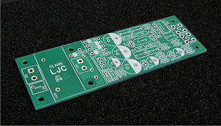
To build the clock you're going to need the same tools as any other PCB based electronics project. It's all through hole, but it's at the finer scale end of through hole, so you are going to need a decent soldering setup and good technique. If you're using leaded solder, a decent electronic specific plug in iron will do, but if you're using lead free solder a soldering station is recommended. The clock uses JFETs and other static sensitive devices so you'll need a static safe workstation. A multimeter and oscilloscope are also useful for checking that the clock is working properly, and are very useful if it isn't. Of course you'll also need the schematic and bill of materials.
There are two versions of this clock, both sharing the same PCB. They differ on how they are powered, one has a transformer and is powered directly from 220 to 240VAC mains electricity (called the AC powered version). The other is smaller, having no transformer, and is powered from a 7 to 20VDC supply, usually an existing supply within a CD player. The DC version draws about 40mA, most CD players will have a supply that can provide that without issue. When building the AC powered version components D205 and J202 are not populated, when building the DC powered version components D201 to D204, J201, TX201 and VR201 are not populated.
The bill of materials lists a very specific set of parts. The column labelled 'Order No.' shows the element 14 (formerly known as Farnell) part number, their site will give the details and data sheet on each part. Here are some comments on parts:
- Film capacitors: Parts C101 to C105 are all Wima FKP2, a stacked polypropylene film and foil type. These are a very high performance capacitor that still have a small footprint. I'd stick to these, other film types may be too large, ceramic types will fit but won't perform as well. C202, C203 C205, C208 and C211 are decoupling capacitors, any 5mm pitch film capacitor with a thickness of 2.5mm or less will do here. I used Wima MKS2 stacked metalised polyester types.
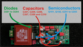
- Electrolytic capacitors: I used Nippon Chemicon KZE low impedance high temperature types, except for C209 which is a KMG general purpose high temperature type. There are plenty of other good options here, such as the DIY favourite Panasonic FMs and FCs or any equivalents from Nichicon, Elna, Rubycon etc. Stick to capacitors from a reputable brand and don't use extremely low impedance types (such as OS-CONs or solid polymer types) for C210. High temperature types are worthwhile, they only cost slightly more and will give better reliability, especially in older power hungry CD players which can run quite warm.
- Diodes: I used MBR1100s for the rectifier (D201 to D204, only used on the AC powered version), similar schottky or soft recovery types will work just as well. D205 (only used on the DC powered version) is a reverse polarity protection diode, use any 1N400x series diode or leave it out if you like to live dangerously.
- Connectors: J101 and J102 are the output connectors. The PCB pattern is a standard RF type and will accommodate SMA, SMB, SMC and other RF connectors. SMB seems to be the defacto standard for clock in audio, so that's what I used, but feel free to use something different. It's best to use factory made cable with these connector, there's a whole load available cheaply on eBay. J201 or J202 is the power input connector (which one you use depends on whether you're building an AC or DC powered version). It's a standard 5mm pitch terminal block pattern, but will fit 5.08mm (0.2") items without any trouble. I'd recommend the screw cage types over the screw and protector types, they just work better.
- Semiconductors: J309s (Q101 and Q102) and TL431s (U201 and U202) are pretty generic easily available semiconductors, my only advice is to stick to good brands (Fairchild, ST Micro, ON Semi, National etc). The AD8561 comparator (U101) is proprietary to Analog devices, and is not pin compatible with any other suitable candidates, so there's no choice to make here. The series regulator (U203) can be any of the xx108x low dropout regulator series (such as LD1085, LM1086 etc). Make sure you buy an adjustable output voltage version, these come in fixed voltage versions as well. I chose these not because they are low dropout, but because they have integrated protection diodes. You can use an LM317, which is pin compatible, but you'll have to tack the protection diodes to the underside of the PCB.
- Resistors: I used Welwyn MFR3 0.125W metal film types. These have body dimensions of 3.5mm long by 2mm diameter, it is essential that this small size is used, the far more common 0.25W types will not fit. The exception is R101 and R102 which are 10MR. Generally 0.125W resistors are not available in resistances this high, so 0.25W Welwyn MH25 types are used here.
- Transformer: The transformer I used is a Myrra 44091. Its form factor is industry standard, and is compatible with the Block VB1.5/2/6 among others.
- Varistor: VR101 is a varistor (used in the AC power version only) that gives the clock some protection from mains voltage spikes, it is optional.
- Crystal: Obviously a critical component in a crystal oscillator. Stick to good brands (I use Citizen) and make sure you get the correct frequency for your application.
Apart from being slightly more difficult to solder than other through hole PCBs due to the small size components, construction is fairly straightforward. I assembled it in the following order:
- First chose the version you are making. The PCB has a silkscreened line where the PCB can be cut if you are going to build the DC version. The photos will show an AC version being built.
- Solder in the axial components (resistors and diodes), paying attention to the polarity of the diodes.
- This point is a good place to pause and test a few things. The two remaining components, U101 and J101 and / or J102 are expensive and cannot be removed once soldered. You can power the clock up and test the rest of it here. First you should double check the polarity of the components shown below:
- After checking the polarities power up the clock in a safe manner. I will not give specific electrical safety advice. If you are not confident in your ability to work safely with mains electricity do not attempt to assemble the AC powered version of this kit. Use an oscilloscope to check the points shown below. A sine wave of the same frequency as the crystal should be visible on the two marked points. The waveforms at the two points will be of opposite phase. Check the voltage of the other point with a multimeter, it should be 5V.
Hopefully you now have a working low jitter clock. Thanks to those who participated in the group buy, enjoy your clocks!
Update (06/05/2014):
This design has been around for over three years now, and it was time for the first major redesign. The main thing I did to improve on the original was to separate the AC power supply from the clock. I found I barely ever built the AC powered version of this clock because it meant having a mains voltage AC cable running through the middle of the player or a long clock output cable, neither work well.
In this version the clock PCB can sit where it's needed, the AC to DC power supply board can sit with the player's original PSU, and an innocuous DC power cable can cross the player. Overall the size has increased a little, but the clock on it's own is smaller, and I think overall it's easier to fit into a player.
As for building it, the new version is essentially the same to build; the main exception is the regulator. In the newer version I've mounted it to the PCB with a machine screw. It's more robust and lower profile. It's easy to assemble, just follow these steps:
- Take the regulator and bend the leads 90° right after the step where the leads become narrower (ignore that the pictures show a LM337, it's just the TO-220 device I had to demonstrate with). Take the supplied M3x10 machine screw and place it through the PCB from below and thread one of the M3 nuts onto it and tighten.
- Place the LM1085 over the machine screw with its legs inside the pads. Place the M3 lock washer over the LM1085 onto the machine screw, then thread the second nut onto the top and tighten. The stack should be: head of M3x10 machine screw, PCB, M3 nut, LM1085 tab, M3 lock washer, M3 nut.
Enjoy this new version of the clock!


Hi Anton, great post! I'm following you since September because, by a rather strange twist of fate, I found right in that period (in a recycle bin) a chopped CD-72 that I put together. Apart from the (infamous) cogwheel tray, it perfectly works and sound great for the age. I'm gonna following your advices and doing my first cd modding (with a little help from a couple of colleagues of mine). The first thing is building the your low jitter clock and then fitting new OpAmps (I want to try the OPA2606 and the AD825) and new Caps, not to mention a new power supply with proper components. I'm trying to get the PBC done but the companies here in CH or in D like to have the Gerber file. Can you please share it? Or even better: you mentioned a "group buy", so I assume that you still have some empty PCB laying around. If so I would happily buy it (doing a single PCS run it's pretty expensive here). Thank you in advance!
ReplyDeleteGlad you like the blog. I'll get in touch with you about the files.
ReplyDelete