
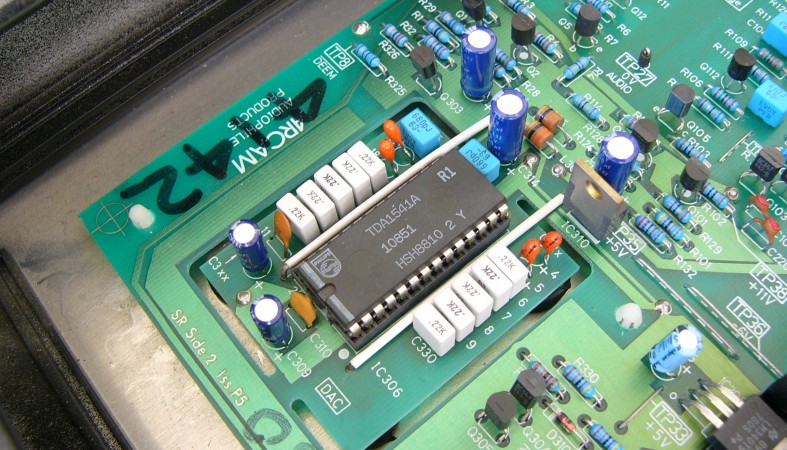
I bought this particular example in non working condition. It was outputting a very low level distorted signal in both channels. As soon as I saw it advertised I already had a good idea about what was wrong with it, a fried TDA1541A DAC integrated circuit. For reasons unknown to me, a handful of high performance devices supplied -6V to the -5V power input (VDD1). The DAC IC will tolerate this in the short term, but over time every TDA1541A supplied with -6V to VDD1 will fail.

I got the Black Box in the post and immediately switched on my oscilloscope and went for a look around inside. Once the input polarity switch* was in the correct position the digital side was worked great, with all four data and clock lines to the DAC IC looking good. All the power supply rails were at their correct voltages and none had excessive ripple. However, there was no output from the DAC IC, as I had suspected it was badly damaged. Conveniently, this unit has its TDA1541A socketed, so it was a simple swap without even needing to use a soldering iron. With a new TDA1541A the unit was making music, and sounding quite good too.


With the Black Box 2 running, I had a look at what else could be done to it. I decided to do the following things:
- Replace the electrolytic capacitors. This type of component has a limited life (usually between 2000 and 4000 hours), after that they won't meet their original specifications. This can cause a number of bad things depending on what they are used for. I usually use Nippon Chemicon electrolytic capacitors, but other brands such as Panasonic and Nichicon will do just as well. I used low impedance LXZ series capacitors to directly decouple the more important ICs, and general purpose KMGs for the remainder.
- Resolder all of the film capacitors. Right before the mainboard of this particular Black Box 2 was wave soldered it had been knocked and many of the components, especially the film capacitors, had been soldered so that the sat at an angle raised about 2 mm off of the PCB. For reliability I resoldered all of these components so that the sat flush on the PCB. It's bad practice to have a component raised off of a PCB like this, the added leverage when exposed to shock and vibration can crack and fail solder joints over time.
- Change the VDD1 power input from -6V to -5V. I don't want the same thing to happen to the replacement TDA1541A, especially as I'll be using a selected S1 grade IC. This is actually a very easy job, the VDD1 rail is regulated by a LM337 negative adjustable voltage regulator. To alter its output I changed resistor R309 from 490R to 360R.
- Upgrade parts of the power supply. The power supply is actually already very good, but there are a couple of improvements I have in mind. The digital section uses three LM7805 fixed regulators. I'm going to replace these with Texas Instruments' TL780-05, a pin compatible regulator with 10dB better ripple rejection. I'm also going to replace the LM7915 that supplies -15V to the TDA1541A with a LM337 and the additional components that requires.
So far I've replaced most of the electrolytic capacitors and changed the VDD1 voltage. I'll report back when it's all done with my verdict on its sound.

* This switch needs to be set to suit each different S/P DIF source. If the Black Box isn't making sound, its the first thing you should check. It's located on the back right next to the coaxial digital input, don't confuse it with the phase switch on the front.
Update (6 March): How the Black Box Sounds
I have now carried out all of the modifications described above, and decided to give it a proper listening test. Overall it sounded extremely good, especially considering its age and how close to stock condition it is.
It was the best TDA1541A based device I had ever heard. It still had all of the characteristics of a TDA1541A DAC, but without many of the flaws. High frequency detail was very good, and so was channel separation. It had no soundstage depth, which wasn't surprising. I also tried it with a TDA1541A S1; the selected grade IC was noticeably better and seemed to have a lower noise floor.
I was pleased with its performance, I think it's earned a permanent place in my system. At the time of its release it must have been an amazing device.
Thank you Anton for this great post !
ReplyDeleteI believe I know why the -VDD1 voltage was set to -6V. Reading early 1985 Datasheet from Philips for the original TDA1541, they listed Max voltage to be -6V. However, on subsequent revision to the TDA1541A, their datasheet lists -VDD1 Max to be -5.5V.
It appears that the Black Box was likely designed for the original version of the chip, and the datasheeet updates for the 'A' were subsequently not noticed.
Question: You mention the 'additional components' required for the LM337. I presume that is the addition of a Variable Resistor for the 'ADJ' pin? Were there any other components that you added/changed to support this replacement ?
That's true, -6V is within the allowable range for a TDA1541, but -5V is the typical supply voltage for both the TDA1541 and TDA1541A.
DeleteFor the LM337 I probably added the two divider resistors, plus a bypass capacitor (which is optional).