- A new laser mechanism. The CDM0 and CDM1 have a prototype feel to them, they're large, they have many parts and are made of expensive materials. The CD150 uses the CDM2. For the CDM2 both the chassis and laser swingarm arm made of plastic and the spindle motor is a much more compact PCB based brushless design.
- An IC based servo. Earlier CD players had complex servos based on discrete semiconductors and low level integration (such as opamps and logic ICs). The CD150 uses the new TDA5708 photodiode signal processor and TDA5809 radial error signal processor ICs. This cut down both the component count and the PCB area the servo occupies.
- A standard PCB layout. This player has three significant PCBs; the servo board (underneath the laser mechanism), the mainboard (on the right side of the player) and the front panel board. Philips made a fair few players during this era with the same layout. Compared to earlier CD players with multiple stacked PCBs these were easier to construct and service.
- A cheaper case. Most of the other changes were positive, this one isn't. The CD150's case is fairly well designed, but it lacks rigidity. When the lid is removed it's laughably flexible, and the larger full width players, like the CD350, are even worse.

As you might notice this image is a bit different to what I normally upload. It's on my workbench, this post will be about how to do a capacitor replacement as well as some basic upgrades. This player is a good candidate, it's stock standard and still working, but it's starting to struggle to read a CD.
Tools
This job requires tools that are specific to electronics. Some are essential, some are optional. We'll start with the essentials:
- A soldering iron. You'll need an iron suited to electronics with a reasonably fine tip with a power of 15 to 30W and a ceramic element. Don't use a large high powered one with a nichrome element, they're best used for burning marks into wood. I used to use an Antex XS25, it was okay. You'll also need a stand and a wet sponge to clean the tip.
- Solder. Leaded solder is easier to work with and more forgiving of poor technique, so I'd recommend that, though I realise it's hard to get anything other than lead free in some places. Whichever you get, make sure it's a good brand solder with multiple flux cores. I use Henkel Multicore 362, 60/40 leaded solder with a rosin flux. The solder diameter should be 0.75mm (22SWG) or less.
- Desoldering tools. There are a couple of options here. You can use either desoldering wick (sometimes called desoldering braid) or a desoldering pump (sometimes called a solder sucker). I mostly use a desoldering pump, maybe take a look at how they're used later in this post to decide which you prefer. For the wick, only buy a name brand, cheap brands don't work. Don't buy brand name wick from China on eBay, it's often counterfeit and again won't work. I use Edsyn Soldasip SW091. Generic solder pumps will work okay, but name brand ones work better. I use an Edsyn Soldapullt SS750LS.
- Cutters. Try to get a pair or proper electronics cutters, rather than diagonal pliers. I use Hakko CHP-170 cutters, they're cheap and they work very well.
- ESD protection. This is an item many overlook, but it's essential, at least if you want the CD player to work after you've finished with it. You're going to need a mat and a wrist strap with a cord.
- Screwdrivers. Most of you will already have a general purpose screwdriver set, but for older Philips players you'll need a Torx T10 driver as well.

Additionally there are a few optional ones:
- A soldering station. An ordinary soldering iron doesn't work very well. If the power is low it will be too cold to solder larger components properly. If the power is to high it'll overheat smaller components and burn of the flux. A soldering station is temperature controller, and varies the power to its soldering iron so that you can solder both larger and small components well. I use a classic Hakko 936, which is a good soldering station. You can pick up one of the second hand market or buy its replacement new, the Hakko FX888. Goot also make nice soldering stations, as do Pace and Metcal, though I only have personal experience with Hakko and Goot.
- Test equipment. In an ideal world you wouldn't need it, but if your repair is unsuccessful, you're blind without it (literally, electrons are very hard to see). The main instruments I'd use when troubleshooting a CD player are a multimeter and an oscilloscope.
Materials
Okay, you've got the tools, now you need the materials. The first step is forming a bill of materials, or BoM (a list of what electronic components you need).


There are a few was to make a BoM. The service manual is available for free online for most of these older Philips players, including the CD150. Nostatech is a great resource for Philips service manuals. You can make the BoM simply by reading the manual, which will list all of the components. However, my prefered method is to remove the PCBs and read the values directly off the capacitors. Often the service manuals won't list the voltage rating (which you need to know), and sometimes aren't consistent with the actual device. When making a BoM for a capacitor replacement you need to note the capacitance and voltage rating of each component. You may also want to note the diameter if the capacitor is in a tightly packed area (so that you don't get a replacement that is to large to fit) and its function. Here is an example, the BoM I wrote for the CD150:
| Mainboard: | ||
| 6800u/16 | 1 | 2416 |
| 1000u/16 | 1 | 2417 |
| 330u/25 | 2 | 2402, 2418 |
| 100u/25 | 1 | 2419 |
| 47u/10 | 7 | 2320 (DAC dec.), 2321 (DAC dec.)2388, 2396 (digital filter dec.), 2397, 2410, 2411 |
| 47u/25 | 10 | 2309, 2362, 2365, 2380 to 2383 (opamp dec.), 2412, 2413, 2414 |
| 100u/10 | 2 | 2384, 2385 (both output coupling) |
| 10u/63 | 2 | 2330, 2331 (both DAC bias filtering) |
| 220u/63 | 1 | 2420 |
| 1u/63 | 1 | 2313 |
| Front: | ||
| 47u/25 | 3 | 2052, 2056, 2058 (all axial) |
| 1u/63 | 1 | 2053 (axial) |
| Servo: | ||
| 47u/10 | 2 | 2104, 2107 |
| 33u/16 | 1 | 2103 |
| 47u/25 | 1 | 2173 |
| 1u/63 | 1 | 2174 |
| 1.5u/50 | 1 | 2159 (bipolar) |
| 220u/10 | 3 | 2127, 2138, 2140 |
As you can see above, I've identified a few capacitors that I'll give special treatment. These are:
- DAC, digital filter and output stage opamp decoupling capacitors (2320, 2321, 2393, 2380 to 2383). These capacitors are located close to their respective components and have a large impact on the quality of power supply that each component sees.
- Coupling capacitors (2384, 2385). These are used to block any DC at the players output, so that the player only outputs AC. These are critical to sound quality. They can be replaced with film capacitors, but their size adds another set of issues, so I'll stick with compact electrolytic capacitors.
- DAC biasing capacitors (2330, 2331). These are part of the circuit that nulls the offset of the DAC ICs current output. A low impedance type will help here.
- Axial capacitors (2052, 2053, 2056, 2058). This form factor, where the leads are attached to both ends of the body, has gone out of common use in favour of radial packages, where both leads are attached to one end of the body. Axial capacitors are used in all three boards in this player, but in most cases a radial capacitor will fit okay. On the front panel board there isn't room to stand a radial capacitor upright, so I'll use axial replacements. You could use radial capacitors, but it will look untidy and possibly be less mechanically reliable.
- Bipolar capacitor (2159). This capacitor filters the output of the radial motor driver, and can cause problems in some cases. I prefer to replace it with a film capacitor, but a replacement bipolar electrolytic will also work.
So that covers the type of capacitors needed, now I need to determine the capacitance and voltage ratings. I won't get replacements that exactly match the originals, it just isn't necessary. When choosing a replacement's capacitance, you should stick to the same value as the original unless you understand what its function is, and the implications of making a change. For example, increasing the value of the four 100uF opamp decoupling capacitors isn't a bad idea, but increasing the value of the 1uF capacitors (part of the microcontroller reset circuit) could disable the player.
When choosing a replacement's voltage rating, in general sticking to a rating the same or higher is fine. However, there are a couple of exceptions:
- Don't increase the voltage rating excessively. If you try to replace a 220uF/10V capacitor with a 220uF/200V one you may find it simply won't fit, as size increases with voltage rating. Electrolytic capacitors also diminish in performance in some respects with voltage rating, the sweet spot is 35V.
- Some capacitors have a voltage rating far higher than necessary. Often these are low capacitance, and are only available in high voltage ratings. An example in the CD150 is the two 1uF/63V capacitors. They only have 5V across them, so it would absolutely fine to replace them with 1uF/50V or 1uF/35V rated capacitors. To consider reducing a voltage rating, you must know exactly what the capacitor will be exposed to.
Now that we've established what capacitances and voltage ratings we need and what special requirements some particular capacitors have we can actually make a final BoM to order. Here's what I came up with for this player:
| 1u/63 | 2 | EKMG500ELL1R0ME11D | Nippon Chemicon |
| 1u/63 | 1 | MAL203038108E3 | Vishay BC |
| 1.5u/50 | 1 | BSME500ELL2R2ME11D | Nippon Chemicon |
| 10u/50 | 2 | ELXY630ELL100MEB5D | Nippon Chemicon |
| 33u/35 | 1 | EKMG350ELL330ME11D | Nippon Chemicon |
| 47u/25 | 3 | MAL203036479E3 | Vishay BC |
| 47u/35 | 13 | EKMG350ELL470ME11D | Nippon Chemicon |
| 56u/35 | 7 | ELXY350ELL560MFB5D | Nippon Chemicon |
| 100u/10 | 2 | UES1E101MPM | Nichicon |
| 100u/35 | 1 | EKMG350ELL101MF11D | Nippon Chemicon |
| 220u/25 | 3 | EKMG350ELL221MHB5D | Nippon Chemicon |
| 220u/50 | 1 | EKMG500ELL221MJC5S | Nippon Chemicon |
| 330u/25 | 2 | EKMG250ELL331MHB5D | Nippon Chemicon |
| 1000u/16 | 1 | EKMG160ELL102MJ16S | Nippon Chemicon |
| 6800u/16 | 1 | EKMG160ELL682MLN3S | Nippon Chemicon |
This list was not only based on what I prefer, but what was available to me at a good price. By default I chose Nippon Chemicon KMG series. These are a general purpose 105°C capacitor from a brand I trust. I normally use 105°C rated capacitors, they're only slightly more expensive than 85°C rated ones, but will last much longer. For the critical decoupling capacitors I chose Nippon Chemicon LXY series, a long life low impedance type. For the DC blocking capacitor I chose Nichicon ES series, a good quality bipolar electrolytic that sounds better than most. For the bipolar capacitor in the servo I chose Nippon Chemicon SME-BP series, a general purpose bipolar type.
You've got to make decisions about what you buy based on what's available to you. It's no use making a list like this without knowing that they'll be in stock at a reasonable price. Which electronics seller will be best for you depends on your location, the following are worth considering; Farnell / element14 / Newark, Digikey, Mouser and RS. These serve the Asia Pacific region, there are more that serve other parts of the world. I also use PartsConnexion for audio-specific components. I don't recommend eBay, it looks good on the surface, but the value coverage and quality is quite patchy.
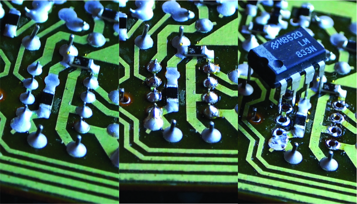
As part of this I'll also replace the output stage opamps. This player originally used LM833s, one per channel. One half is the I/V converter, the other half is a buffer. Though most modern dual opamps in an 8DIP package share the same pinout, they're not universally interchangable. I decided on an OPA2134 as a replacement, it has good performance, it is not too fast, it is unity gain stable (the buffer has unity gain) and it is widely available. There are many good opamps, but unless you understand what to look for in a replacement and have an oscilloscope to check for stability, I'd stick to the OPA2134.
As part of this I'll also replace the output stage opamps. This player originally used LM833s, one per channel. One half is the I/V converter, the other half is a buffer. Though most modern dual opamps in an 8DIP package share the same pinout, they're not universally interchangable. I decided on an OPA2134 as a replacement, it has good performance, it is not too fast, it is unity gain stable (the buffer has unity gain) and it is widely available. There are many good opamps, but unless you understand what to look for in a replacement and have an oscilloscope to check for stability, I'd stick to the OPA2134.
Desoldering
Now that you've got a pile of fresh capacitors, it's time to remove the old ones. The boards in this player are actually double sided, but they're not through hole plated, so the techniques are the same as what you'd use on a single sided board. At the same time you're desoldering the components you'll need to think about how you'll know what values go where and their polarity when you come to soldering in the new capacitors. The easiest way is to only desolder and replace one value at a time.
To note polarity you can mark the board (I put a dot next to the negative lead, the one marked by a stripe or ring on the capacitor). I also like to take a photo before the replacement that I can compare with the end result. It's best to rely on these method rather than to use the diagram in the service manual or the board's silkscreen (on more modern PCBs than this example), as both of these are often wrong. The service manual digram for the CD150 shows the wrong polarity for both 2380 and 2309.
On these types of boards I'll use two different techniques, depending on how the components were mounted. For smaller components, like resistors, diodes, TO-92 transistors and electrolytic capacitor less than 8mm, the legs of the components were bent over to hold them to the board during wave soldering. Larger, heavier components were simply placed, their own weight would be adequate to keep them in place.

On the smaller components, the leads are usually accessible from the top side. I cut the leads as close to the board from the top side. I then add fresh solder to the joints from the bottom side then remove both the solder and lead remained using the desoldering pump.

On the larger components, where the leads aren't bent, I'll add solder to the joints from the topside, then use a desoldering pump to remove the solder. If this is done cleanly, the component should pull out easily from the top, or even drop out. If the component isn't free, check that each lead is loose when pressed with, say, a fine screwdriver. Add fresh solder and reapply the desoldering pump as necessary to free each lead.
Soldering
Like I mentioned above, you'll probably want to install the new components as you remove the old ones. How to solder is something that has been done many times, this video here is quite good, if you're unfamiliar with soldering I suggest you watch it. The main thing is to check that the component you're installing is the right value and the polarity is correct.
Unfortunately these older PCBs are quite fragile. When you're desoldering components it's easy to damage the tracks or pads on the board. If you do this, don't ignore it. the best way to fix the problem is to bend the lead through the damaged pad and solder it to another pad that it would normally be soldered to. Even though I was very careful with the CD150's board, half of a pad on one of the capacitors lifted. Here is a photo of how I repaired that:

Here are the boards after the replacement:

To note polarity you can mark the board (I put a dot next to the negative lead, the one marked by a stripe or ring on the capacitor). I also like to take a photo before the replacement that I can compare with the end result. It's best to rely on these method rather than to use the diagram in the service manual or the board's silkscreen (on more modern PCBs than this example), as both of these are often wrong. The service manual digram for the CD150 shows the wrong polarity for both 2380 and 2309.
On these types of boards I'll use two different techniques, depending on how the components were mounted. For smaller components, like resistors, diodes, TO-92 transistors and electrolytic capacitor less than 8mm, the legs of the components were bent over to hold them to the board during wave soldering. Larger, heavier components were simply placed, their own weight would be adequate to keep them in place.

On the smaller components, the leads are usually accessible from the top side. I cut the leads as close to the board from the top side. I then add fresh solder to the joints from the bottom side then remove both the solder and lead remained using the desoldering pump.
On the larger components, where the leads aren't bent, I'll add solder to the joints from the topside, then use a desoldering pump to remove the solder. If this is done cleanly, the component should pull out easily from the top, or even drop out. If the component isn't free, check that each lead is loose when pressed with, say, a fine screwdriver. Add fresh solder and reapply the desoldering pump as necessary to free each lead.
Soldering
Like I mentioned above, you'll probably want to install the new components as you remove the old ones. How to solder is something that has been done many times, this video here is quite good, if you're unfamiliar with soldering I suggest you watch it. The main thing is to check that the component you're installing is the right value and the polarity is correct.
Unfortunately these older PCBs are quite fragile. When you're desoldering components it's easy to damage the tracks or pads on the board. If you do this, don't ignore it. the best way to fix the problem is to bend the lead through the damaged pad and solder it to another pad that it would normally be soldered to. Even though I was very careful with the CD150's board, half of a pad on one of the capacitors lifted. Here is a photo of how I repaired that:


Powering Up
Now the the repair is complete it needs to be tested. I recommend that you once again check that all the components are installed with the correct polarity. If the polarity is wrong the electrolytic capacitors may explode, and the opamps would be destroyed.
Reassemble the boards into the player and reconnect the cables. If you're unsure about the cabling, check the wiring diagram in the manual. You should also check the motion of the laser mechanism's swingarm when you have screwed the servo board to it. It should swing freely throughout its arc, if it doesn't you may have installed a capacitor that is too tall. If that is the case, remount the capacitor on its side or use an axial leaded capacitor.

When testing a new repair, it is good practice to slowly power it up using a variac while monitoring its current consumption. However, a CD player is a low power appliance, so that's not strictly necessary. If you don't have a variac, power the player up while wearing safety glasses and prepare to turn it back off if anything sounds, smells or looks wrong. Don't connect the outputs to anything during this first power up.
If all goes well, connect the player to the rest of your sound system, put a disc in and try it out. Check it plays both pressed CDs and burned CD-Rs and check it plays well without skipping from the first to the last tracks. Hopefully it all works fine. If it doesn't, it's troubleshooting time. A CD player is a fairly complex piece of electronics, so troubleshooting a bad repair is going to be a hard ask for a beginner. It's best to start out with a cheaper player like a CD150, wrecking one of these is no great loss. Wrecking something like a Marantz CD16 on the other hand... (I've had to recover one of these from a upgrade gone wrong before).
Hi Anton - I am making progress. Picked up a one owner Marantz CD5000 - I will enjoy it stock for a while but have decided that rather than have other people do any upgrades I will start the learning curve and have a go myself. Two questions: I gather you are not impressed by adding a tube stage - was there no real benefit, or did a solid state buffer work just as good, or do you think a buffer is not needed. secondly, are your clocks still available, or is there a commercial one you now recommend? Thanks -Paul W
ReplyDeleteHi Paul,
DeleteThe tube output stage sounded very good, my criticism was that the same thing could be achieved by other means without the bulk, heat and high power requirements of tubes. The space and heat aren't going to be a problem in a CD5000 though.
Apart from the space, I'm not sure why you chose a Marantz CD5000. That's a very cheap player with a fairly mediocre DAC. That's not to say you won't be able to make it sound okay, but when I put a lot of time and effort into a player I prefer to start with something better.
I do still have PCBs for my clock available.
I'm happy to help you with this project, but it might be better to do it by email rather than here.
Thanks,
Anton
Hi Anton - simple answer to why - this guy raves over the DAC either stock or tubed.
ReplyDeletehttp://lampizator.eu/LAMPIZATOR/REFERENCES/Marantz%20CD5000/marantz5000.html
Of course its a matter of personal taste for sound but he was my main reason.
Re email - how do we do that?
-Paul
Yeah, while the site is very useful, his observations on sound quality don't line up with my own. Besides that, I chose players for their build quality as well as sound quality.
DeleteMy email is shown on my Blogger profile.
Thanks,
Anton
Hello Anton. Thanks for your very interesting tutorial. I get a Philips CD150 from a friend and want to modify it. I also shot a Philips CD 720 for less than 20€ including shipping and was impressed about his sound. It's sounds better than my old one and better than the CD150.
ReplyDeleteWhat do you think about changing the diode to schottky type? Which ones would you choose?
Greetings,
Mike
It's not something I always change, but it's not a bad idea. I would use an MBR1100, there's nothing special about these, they're just the standard 1A schottky diode I use.
DeleteThanks,
Anton
hi anton,
ReplyDeletei recently received an cd 150 and when i turned it on, the diodes (of the power supply i guess) began to smoke. i tried to find a plan of this apparatus to see, which spare parts i need without success. maybe you can help me. my idea was to turn off the oversampling for more delicious audio, but now i have to fix this problem first - what may be the reason for the diodes to burn up in smoke and what type of parts do i need?
i hope you answer - best regards, dirk
Hi Dirk,
DeleteI'd expect to find something shorted on the power supply rail that those diodes are part of. Before ordering spares you'll need to find exactly which diodes have overheated, what they're supplying and what is shorted. It's probably something on one of the unregulated supplies, as the current limiting function of the regulators would have prevented this happening on a regulated supply.
It'd be best to email me directly for more detailed information, just leave me your address.
Thanks,
Anton
hi and thank you,
ReplyDeleteguess it will be hard to find the mistake. is it possible that the transformator is shorted, because it made a humming noise before the diodes began to smoke. i would be glad if you can send me the plan for the cd 150. here my email: dirkwalter@online.de
regards
Reply with next question below.
Deletehi,
ReplyDeletetoday i found that the biggest of the capacitators (6800µF 16V) has no resistance. my multimeter said that current is going through in both directions. i guess it must be reason, isn`t it? i hope the transistor that is fixed to the aluminium cooler survived - it will be tested at the shop where i get my spare parts. what do you say to this diagnosis? email to: dirkwalter@online.de
regards
Hi Dirk,
DeleteThe transformer will hum when heavily loaded, if this happens again you should immediately unplug the player. I hope it hasn't been damaged, as it's a hard part to replace.
A properly working capacitor when measured with a ohmmeter should initially read low resistance, increasing until it reads open circuit. If by "no resistance" you mean 0Ω, then that's a problem. The TO-220 device attached to the heatsink is a voltage regulator rather than a transistor, and it's most likely okay. I'll contact you with more information.
Thanks,
Anton
Hi Anton,
ReplyDeleteI read with interest your blog on cd150 modding, as I have a cd350 with almost identical main pcb and have refreshed capacitors in the power supply area with panny FM/FC and swapped the DC blocking caps for muse ES types with great results ! I am now concentrating my efforts on the DACs and other digital chips, which I am treating to some low impedance types (rubycon ZLG) close to their power supply pins - as from my understanding these low esr types help to fill in any gaps in voltage fluctuations caused by the chips internal switching noise, am I going about this in the right way ?
Also you mention caps 2330/2331 as per TDA1540 datasheet being part of the back bias supply voltage circuit and low impedance types being important here too, but I don't understand why ? Some other chips on this player have a similar back bias circuit, would low esr types help "tune" these chips too ??
All suggestions greatly appreciated - thank you.
Richard.
Hi Richard,
DeleteCapacitors 2330 and 2331 aren't back bias supply decoupling capacitors. The output current of the TDA1540 (and TDA1541) is offset, ranging from 0 to -4mA, with silence being -2mA. Resistors 3330 to 3333 are connected to a positive supply, drawing roughly enough current out of the DAC's output to shift the silence current to 0mA. 2330 and 2331 form filters with those resistors to ensure that noise from that positive supply doesn't make its way into the output node.
The back bias supply on the digital ICs used in the CD150 is completely unrelated. Back biasing was a technique to reduce the rather horrific power consumption of these older ICs. Very little current is drawn from the VBB supply, I wouldn't worry about it.
Thanks,
Anton
Hi Virgil,
ReplyDeleteWhen you say 'all checked fine on a capacitance meter', what were you checking? The issue with these capacitors is not a loss of capacitance, but an increase in equivalent series resistance (ESR). They'll check out okay using the capacitance mode on a regular multimeter, an LCR meter is needed to check the ESR and get an accurate picture of the health of the capacitors.
In any case, I'd replace them anyway. They've either failed, or are close to failure.
Thanks,
Anton
8.4Ω is a bit high, and needs replacing, that's probably about twice what is was when it was new. The others do seem fine, assuming the meter is accurate. Did the CDP's behavior change at all after replacing the 47µF/25V capacitor?
ReplyDeleteI myself would still replace the rest of the electrolytic capacitors in the CDP, but it's not necessarily critical to the repair.
The next step I would take is checking the laser power and focus offset adjustments and measuring the laser current (via the voltage drop over 3101, a 12Ω resistor).
Let me know how you go,
Anton
Hi Anton
ReplyDeleteI am using your guide to practise on a 150 before tackling my more valued Arcam Alpha plus.
I have made a BOI using your list as a start but checking each component against the actual boards. In doing this I have come across a discrepancy. I would be grateful for your advice as I don't have enough knowledge to make sense of it.
You list cap 2127 on the servo board with 2138 and 2140 as 220u/10v. On my board 2127 is 47u/10v. On the negative side it is attached to 2 resistors in series with a connection to a pcb track between the resistors. On the positive it is attached to one resistor and to a pcb track. (If it is relevant, 2138 and 2140 are 220u/16v vs 10v).
The 2127 cap has a coating of a white dusty residue so I assume it is failing. (Likewise the bipolar 1.5u/50v on the servo and 2 0f the 47u/10v on the main board) However the cd player reads and plays discs well and sounds pretty good.
I am not sure if the values you gave for 2127 were a typo or if the cap value might vary if attached to different resistors? I assume that I should replace 2127 with the same values as on my board ie 47u/10v but I would be grateful for your advice.
Thanks and best wishes,
Martin
We're probably both right.
DeletePhilips made many changes to component values during production of these early CD players. Sometimes they would use a revision letter system, and you'd see revisions going as high as K, each the same PCB with different modifications and component values. I'd stick to what's already there with the version of the board you have.
Hi Anton,
ReplyDeleteThanks for your earlier advice on getting started. Based on that I am practising on a CD150 before working on my Arcam Alpha Plus. I have replaced all the caps on the servo board and, it works!!
I would be very grateful for advice on a capacitor replacement/substitution on the main board. 2414 is 33uF 40volt. Would it be ok to replace it with a 47uF 35volt?
Cheers,
Martin
Glad to hear your repair was successful.
DeleteIn general I'd avoid replacing a capacitor with another of a lower voltage rating, unless there is a very good reason. In this case 2414 is on the output of a 18V regulator, which sounds okay, but if the regulator fails (which can happen) it could be exposed to a 33V unregulated rail. With variation, that's too high for a 35V rated part. I'd stick to 40 or 50V rated part. 33 or 47uF are both fine.
Remember that an electrolytic capacitor will explode if exposed to voltages much over rated. The difference in cost between a 35 and 50V rated electrolytic is minimal, so it's worth being cautious and knowing a failed regulator won't lead to a bang.
Hi Anton,
ReplyDeleteNo more questions. I have used enough of your time!
I just want to say, thank you. I have completed the cap replacement on the CD150 using your advice. Firstly it works and secondly it sounds so much better than before.
Thanks and best wishes,
Martin